

Annotated Code Overview
The annotated code overview aims to give an IPython Notebook style introduction to the C++ codebase for the project. As there is no IPython Notebook equivalent for C++, none of the code is directly runnable, but having it mixed with full commentary can help in providing a fuller understanding of the codebase. In unimportant places, source code will be elided for the sake of succinctness. In important sections, additional explanation beyond what the code itself provides may be used.
Boilerplate (elided)
// ==Montelight==
// Tegan Brennan, Stephen Merity, Taiyo Wilson
#include <cmath>
#include <string>
#include <iomanip>
#include <iostream>
#include <fstream>
#include <sstream>
#include <vector>

#define EPSILON 0.001f

using namespace std;

// Globals
bool EMITTER_SAMPLING = true;
Vectors
In our task, all interactions happen in a three dimensional space: points or colors. The most convenient representation for this is a three dimensional Vector. For succinctness, and to prevent duplication of equivalent functionality, the Vector class is used for both points in space as well as the colors. Whilst many of the operations we perform on Vectors are obvious (min, max, addition, subtraction, etc) there are some that warrant special attention.
Vectors for points
When dealing with vectors as points in space, we perform two primary operations: dot product and norm.
The dot product of two vectors $X$ and $Y$ is $X \cdot Y = |X| |Y| \cos{\theta}$, represented in the code as X.dot(Y).
When we normalize the vectors $X$ and $Y$ beforehand such that $|X| = |Y| = 1$, that means the dot product is equal to the angle between the vectors.
This is used to work out angle of incidence and reflection, primarily for calculating the Bidirectional Reflectance Distribution Function (BRDF).
The other common operation is working out the direction of travel if we are at point $X$ and wish to reach point $Y$.
An example might be if we want to work out what direction a ray should be shot from a surface point $P$ in order to reach a point on a light source $L$ assuming the surface point is not in shadow.
Thanks to the Vector class, this can be intuitively written as (L - P).norm().
Vectors for colors
When it comes to light or pixels, we represent colour as a Vector of [red|green|blue].
This Vector is limited to the range $[0, 1]$ such that we can scale it arbitrarily later.
As some light sources can exceed our perceived vision (i.e. greater than 1) we clamp the values to the correct range.
This is accurate to our physical models (both eyes and cameras resort to white when oversaturated with photons) and also helps prevent anti-aliasing.
struct Vector {
  double x, y, z;
  //
  Vector(const Vector &o) : x(o.x), y(o.y), z(o.z) {}
  Vector(double x_=0, double y_=0, double z_=0) : x(x_), y(y_), z(z_) {}
  inline Vector operator+(const Vector &o) const {
    return Vector(x + o.x, y + o.y, z + o.z);
  }
  inline Vector &operator+=(const Vector &rhs) {
    x += rhs.x; y += rhs.y; z += rhs.z;
    return *this;
  }
  inline Vector operator-(const Vector &o) const {
    return Vector(x - o.x, y - o.y, z - o.z);
  }
  inline Vector operator*(const Vector &o) const {
    return Vector(x * o.x, y * o.y, z * o.z);
  }
  inline Vector operator/(double o) const {
    return Vector(x / o, y / o, z / o);
  }
  inline Vector operator*(double o) const {
    return Vector(x * o, y * o, z * o);
  }
  inline double dot(const Vector &o) const {
    return x * o.x + y * o.y + z * o.z;
  }
  inline Vector &norm(){
    return *this = *this * (1 / sqrt(x * x + y * y + z * z));
  }
  inline Vector cross(Vector &o){
    return Vector(y * o.z - z * o.y, z * o.x - x * o.z, x * o.y - y * o.x);
  }
  inline double min() {
    return fmin(x, fmin(y, z));
  }
  inline double max() {
    return fmax(x, fmax(y, z));
  }
  inline Vector &abs() {
    x = fabs(x); y = fabs(y); z = fabs(z);
    return *this;
  }
  inline Vector &clamp() {
    // C++11 lambda function: http://en.cppreference.com/w/cpp/language/lambda
    auto clampDouble = [](double x) {
      if (x < 0) return 0.0;
      if (x > 1) return 1.0;
      return x;
    };
    x = clampDouble(x); y = clampDouble(y); z = clampDouble(z);
    return *this;
  }
};
Rays
In raytracing, our definition of a ray is quite simple. We tie together two Vectors to form a ray: position and direction. The ray can either extend to $\infty$ in the given direction or extend to the end of the direction vector itself. The latter might be useful if we wish to say that a ray hits a surface $n$ units in this given direction.
Almost no logic is done on the ray class itself. Rays primarily provide a convenient way to pass around information. When rays are modified, their origin usually remains constant and only their direction is modified.
struct Ray {
  Vector origin, direction;
  Ray(const Vector &o_, const Vector &d_) : origin(o_), direction(d_) {}
};
Image
Storing and using samples
The image class is where we store the Monte Carlo samples from our scene. As you would expect, an image is defined by a given width and height, with each pixel in the grid of $width \times height$ being a Vector of [red|green|blue]. When we take a new sample, we save the result by adding the raw red, green, and blue values to the relevant location in the $pixels$ array. We also add one to the number of $samples$ taken at that point such that we can work out the mean later. This allows us to trivially compute the expected mean over the number of samples by: $$ Pixel(x, y) = \frac{Vector_{rgb}(x, y)}{Samples(x, y)} = \frac{1}{N} \sum Vector_{rgb}(x, y) $$
Variance reduction helpers
For use in our variance reduction attempts, we also keep track of the current value of a given pixel at $current(x, y)$ and also record the raw samples for a given pixel in $raw\_samples(x, y)$. We found in our experiments that keeping track of the raw samples leads to excessive overhead however, usually leading to worse results than just taking more samples in the time that would be have been spent performing bookkeeping.The function $getSurroundingAverage$, whilst it isn't used in this code (our experiments showed it to be of little benefit for a large amount of extra computational work), is used for variance reduction through rejection sampling. The intuition was that most pixels are similar to their neighbours. Aliasing occurs when pixels change values sharply. Thus, pixels which are quite different to their neighbours should likely receive more samples. This is similar to attempting to minimize between chain variance in traditional Markov Chain Monte Carlo.
Exporting the image
In order to export the final image, an image format was required. Rather than using a complex format that would require an external library, we chose the PPM format. The PPM is one of the simplest image formats to exist and consists entirely of an ASCII file that consists of 3 sets of numbers for each pixel -- red, green, and blue. Thanks to this, it is easy to write an exporter by hand and doesn't require any complex compression or encoding algorithms. The details of this function is in the $save$ function.
The $toInt$ function is used to convert the Vector of [red|green|blue] into a final set of pixel values. The $toInt$ function performs gamma correction ($x ^ \frac{1}{2.2}$) and then scales the float, which is between 0 and 1, to be from 0 to 255. This allows us to represent the pixel in 24 bit color (8 bits per pixel component) for the final image.
struct Image {
  unsigned int width, height;
  Vector *pixels, *current;
  unsigned int *samples;
  std::vector<Vector> *raw_samples;
  //
  Image(unsigned int w, unsigned int h) : width(w), height(h) {
    pixels = new Vector[width * height];
    samples = new unsigned int[width * height];
    current = new Vector[width * height];
    //raw_samples = new std::vector<Vector>[width * height];
  }
  Vector getPixel(unsigned int x, unsigned int y) {
    unsigned int index = (height - y - 1) * width + x;
    return current[index];
  }
  void setPixel(unsigned int x, unsigned int y, const Vector &v) {
    unsigned int index = (height - y - 1) * width + x;
    pixels[index] += v;
    samples[index] += 1;
    current[index] = pixels[index] / samples[index];
    //raw_samples[index].push_back(v);
  }
  Vector getSurroundingAverage(int x, int y, int pattern=0) {
    unsigned int index = (height - y - 1) * width + x;
    Vector avg;
    int total;
    for (int dy = -1; dy < 2; ++dy) {
      for (int dx = -1; dx < 2; ++dx) {
        if (pattern == 0 && (dx != 0 && dy != 0)) continue;
        if (pattern == 1 && (dx == 0 || dy == 0)) continue;
        if (dx == 0 && dy == 0) {
          continue;
        }
        if (x + dx < 0 || x + dx > width - 1) continue;
        if (y + dy < 0 || y + dy > height - 1) continue;
        index = (height - (y + dy) - 1) * width + (x + dx);
        avg += current[index];
        total += 1;
      }
    }
    return avg / total;
  }
  inline double toInt(double x) {
    return pow(x, 1 / 2.2f) * 255;
  }
  void save(std::string filePrefix) {
    std::string filename = filePrefix + ".ppm";
    std::ofstream f;
    f.open(filename.c_str(), std::ofstream::out);
    // PPM header: P3 => RGB, width, height, and max RGB value
    f << "P3 " << width << " " << height << " " << 255 << std::endl;
    // For each pixel, write the space separated RGB values
    for (int i=0; i < width * height; i++) {
      auto p = pixels[i] / samples[i];
      unsigned int r = fmin(255, toInt(p.x)), g = fmin(255, toInt(p.y)), b = fmin(255, toInt(p.z));
      f << r << " " << g << " " << b << std::endl;
    }
  }
  void saveHistogram(std::string filePrefix, int maxIters) {
    std::string filename = filePrefix + ".ppm";
    std::ofstream f;
    f.open(filename.c_str(), std::ofstream::out);
    // PPM header: P3 => RGB, width, height, and max RGB value
    f << "P3 " << width << " " << height << " " << 255 << std::endl;
    // For each pixel, write the space separated RGB values
    for (int i=0; i < width * height; i++) {
      auto p = samples[i] / maxIters;
      unsigned int r, g, b;
      r= g = b = fmin(255, 255 * p);
      f << r << " " << g << " " << b << std::endl;
    }
  }
  ~Image() {
    delete[] pixels;
    delete[] samples;
  }
};
Shapes
In order to define our scene, we need to state where objects are located in space and their properties. Whilst we only define Spheres in our renderer, we wanted to allow for arbitrary surfaces such as triangles, planes, and any surface that can be mathematically defined. To implement a Shape, all that is required is a way of performing intersection testing, a way to randomly select a point on the surface for use in lighting, and a way to get the normal of any ray that strikes the surface.
struct Shape {
  Vector color, emit;
  //
  Shape(const Vector color_, const Vector emit_) : color(color_), emit(emit_) {}
  virtual double intersects(const Ray &r) const { return 0; }
  virtual Vector randomPoint() const { return Vector(); }
  virtual Vector getNormal(const Vector &p) const { return Vector(); }
};
Spheres
Spheres are the shape we use to define our scenes and test our renderer. Performing intersection tests for an arbitrary ray is a trivial result of applying linear algebra. For more details, refer to any well known resource on rendering that covers ray-sphere intersections. In brief, the calculation uses the quadratic formula to find zero, one or two roots. Zero roots means the ray does not intersect with the sphere. One root means the ray hits the sphere at a tangent. Two roots means that the ray passes through the sphere, with the smaller of the two solutions being the side closest to the origin of the ray.
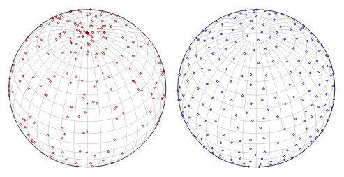
On the left are random points generated using spherical co-ordinates.
On the right are random points generated using computationally intensive Poisson-disc sampling.
Image from Random Points on a Sphere by Jason Davies.
For calculating a random point on the sphere, we use spherical co-ordinates. Whilst this does result in an un-even distribution, it is not a cause of any strong rendering artifacts or issues. Whilst we would have preferred better methods to generate an even distribution of points across the sphere, such as Poisson-disc sampling, they are generally regarded as too slow to compute for real time or computationally intensive applications. Recently Dunbar et al. (2006) proposed using a set of spatial data structures for fast Poisson disk sample generation but this would have been far more complexity than we would want to implement for no real benefit.
struct Sphere : Shape {
  Vector center;
  double radius;
  //
  Sphere(const Vector center_, double radius_, const Vector color_, const Vector emit_) :
    Shape(color_, emit_), center(center_), radius(radius_) {}
  double intersects(const Ray &r) const {
    // Find if, and at what distance, the ray intersects with this object
    // Equation follows from solving quadratic equation of (r - c) ^ 2
    // http://wiki.cgsociety.org/index.php/Ray_Sphere_Intersection
    Vector offset = r.origin - center;
    double a = r.direction.dot(r.direction);
    double b = 2 * offset.dot(r.direction);
    double c = offset.dot(offset) - radius * radius;
    // Find discriminant for use in quadratic equation (b^2 - 4ac)
    double disc = b * b - 4 * a * c;
    // If the discriminant is negative, there are no real roots
    // (ray misses sphere)
    if (disc < 0) {
      return 0;
    }
    // The smallest positive root is the closest intersection point
    disc = sqrt(disc);
    double t = - b - disc;
    if (t > EPSILON) {
      return t / 2;
    }
    t = - b + disc;
    if (t > EPSILON) {
      return t / 2;
    }
    return 0;
  }
  Vector randomPoint() const {
    // TODO: Improved methods of random point generation as this is not 100% even
    // See: https://www.jasondavies.com/maps/random-points/
    //
    // Get random spherical coordinates on light
    double theta = drand48() * M_PI;
    double phi = drand48() * 2 * M_PI;
    // Convert to Cartesian and scale by radius
    double dxr = radius * sin(theta) * cos(phi);
    double dyr = radius * sin(theta) * sin(phi);
    double dzr = radius * cos(theta);
    return Vector(center.x + dxr, center.y + dyr, center.z + dzr);
  }
  Vector getNormal(const Vector &p) const {
    // Point must have collided with surface of sphere which is at radius
    // Normalize the normal by using radius instead of a sqrt call
    return (p - center) / radius;
  }
};
Test scenes
Our test scenes are all based on the Cornell box. Each scene defined as a vector of Shape objects, in our case they are all Sphere objects, including the walls, which are just positioned and scaled so as to appear approximately flat in our scene. The first scene, simpleScene is the standard Cornell box scene, but with a custom light source positioned near the ceiling. The second scene, complexScene contains three spheres located at different distances from the camera. From the point of view of the camera, the edges of the three spheres overlap. If the focal length is set properly with a sufficiently narrow depth of field, this scene should make it easy to observe the focusing effect.
// Set up our testing scenes
// They're all Cornell box inspired: http://graphics.ucsd.edu/~henrik/images/cbox.html
/////////////////////////
// Scene format: Sphere(position, radius, color, emission)
/////////////////////////
std::vector<Shape *> simpleScene = {
  // Left sphere
  new Sphere(Vector(1e5+1,40.8,81.6), 1e5f, Vector(.75,.25,.25), Vector()),
  // Right sphere
  new Sphere(Vector(-1e5+99,40.8,81.6), 1e5f, Vector(.25,.25,.75), Vector()),
  // Back sphere
  new Sphere(Vector(50,40.8, 1e5), 1e5f, Vector(.75,.75,.75), Vector()),
  // Floor sphere
  new Sphere(Vector(50, 1e5, 81.6), 1e5f, Vector(.75,.75,.75), Vector()),
  // Roof sphere
  new Sphere(Vector(50,-1e5+81.6,81.6), 1e5f, Vector(.75,.75,.75), Vector()),
  // Traditional mirror sphere
  new Sphere(Vector(27,16.5,47), 16.5f, Vector(1,1,1) * 0.799, Vector()),
  // Traditional glass sphere
  new Sphere(Vector(73,16.5,78), 16.5f, Vector(1,1,1) * 0.799, Vector()),
  // Light source
  //new Sphere(Vector(50,681.6-.27,81.6), 600, Vector(1,1,1) * 0.5, Vector(12,12,12))
  new Sphere(Vector(50,65.1,81.6), 8.5, Vector(), Vector(4,4,4) * 100) // Small = 1.5, Large = 8.5
};
/////////////////////////
std::vector<Shape *> complexScene = {
  new Sphere(Vector(1e5+1,40.8,81.6), 1e5f, Vector(.75,.25,.25), Vector()), // Left
  new Sphere(Vector(-1e5+99,40.8,81.6), 1e5f, Vector(.25,.25,.75), Vector()), // Right
  new Sphere(Vector(50,40.8, 1e5), 1e5f, Vector(.75,.75,.75), Vector()), // Back
  new Sphere(Vector(50, 1e5, 81.6), 1e5f, Vector(.75,.75,.75), Vector()), //Bottom
  new Sphere(Vector(50,-1e5+81.6,81.6), 1e5f, Vector(.75,.75,.75), Vector()), // Top
  new Sphere(Vector(20,16.5,40), 16.5f, Vector(1,1,1) * 0.799, Vector()),
  new Sphere(Vector(50,16.5,80), 16.5f, Vector(1,1,1) * 0.799, Vector()),
  new Sphere(Vector(75,16.5,120), 16.5f, Vector(1,1,1) * 0.799, Vector()),
  new Sphere(Vector(50,65.1,40), 1.5, Vector(), Vector(4,4,4) * 100), // Light
  new Sphere(Vector(50,65.1,120), 1.5, Vector(), Vector(4,4,4) * 100), // Light
};
//
Tracer
The Tracer class is responsible for handling all ray and light path calculations in the scene. This is broken up into the $getIntersection$ and $getRadiance$ function.
The $getIntersection$ function takes a ray and returns the distance to the first object the ray hits, or NULL if no object is hit.
struct Tracer {
  std::vector<Shape *> scene;
  //
  Tracer(const std::vector<Shape *> &scene_) : scene(scene_) {}
  std::pair<Shape *, double> getIntersection(const Ray &r) const {
    Shape *hitObj = NULL;
    double closest = 1e20f;
    for (Shape *obj : scene) {
      double distToHit = obj->intersects(r);
      if (distToHit > 0 && distToHit < closest) {
        hitObj = obj;
        closest = distToHit;
      }
    }
    return std::make_pair(hitObj, closest);
  }
The core of the raytracer is the $getRadiance$ function, which returns a sample of the amount of light coming in from a set direction when given a ray. This is where the logic for BRDF sampling, explicit light sampling, and Russian roulette path termination occur.
The rejection sampling for Russian roulette path termination occurs when we test U > hitObj->color.max().
We sample a random number $U \in [0, 1]$ and take the maximum color component of the object, where the color components are confined to $[0, 1]$.
If the object is dark and absorbs the majority of light that reaches it, the probability for path termination is high.
Conversely, if the object reflects all of any of the color components, it has a zero probability of terminating the path at that point.
If the path is terminated, we return a zero light contribution (as Vector() defaults to all zeroes, or black).
  Vector getRadiance(const Ray &r, int depth) {
    // Work out what (if anything) was hit
    auto result = getIntersection(r);
    Shape *hitObj = result.first;
    // Russian Roulette sampling based on reflectance of material
    double U = drand48();
    if (depth > 4 && (depth > 20 || U > hitObj->color.max())) {
      return Vector();
    }
    Vector hitPos = r.origin + r.direction * result.second;
    Vector norm = hitObj->getNormal(hitPos);
    // Orient the normal according to how the ray struck the object
    if (norm.dot(r.direction) > 0) {
      norm = norm * -1;
    }
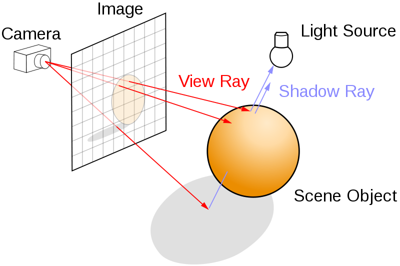
For explicit light sampling, we first check if it is enabled.
If it is, we sample a random point from each light in the scene and check if it illuminates the current hit surface.
To work out the direction to the light, we use the trick described earlier, (lightPos - hitPos).norm().
With that, we can describe a ray from the hit surface towards the light source via Ray(hitPos, lightDirection).
We then check if the given ray immediately hits the light source.
If it hits any other object, we know the object is in shadow, and receives no direct light contribution from that point.
This is well visualized by the diagram below.
The rays that hit the top of the sphere are illuminated by the light source as there is nothing between it and the light.
The ray that hits underneath the sphere first hits the sphere when travelling towards the light source, so we know it is in shadow.
If the hit surface is illuminated by the random point on the light, we calculate the angle towards it using the other vector trick mentioned earlier, lightDirection.dot(norm).
This calculates the angle between the normal of the hit surface and the light source, $\cos{\theta}$.
Then we employ a simple BRDF to approximate how much of the light would be sent from the light source to this specific hit surface.
For more details about the BRDF, refer to An Introduction to BRDF-Based Lighting or our paper.
    // Work out the contribution from directly sampling the emitters
    Vector lightSampling;
    if (EMITTER_SAMPLING) {
      for (Shape *light : scene) {
        // Skip any objects that don't emit light
        if (light->emit.max() == 0) {
          continue;
        }
        Vector lightPos = light->randomPoint();
        Vector lightDirection = (lightPos - hitPos).norm();
        Ray rayToLight = Ray(hitPos, lightDirection);
        auto lightHit = getIntersection(rayToLight);
        if (light == lightHit.first) {
          double wi = lightDirection.dot(norm);
          if (wi > 0) {
            double srad = 1.5;
            //double srad = 600;
            double cos_a_max = sqrt(1-srad*srad/(hitPos - lightPos).dot(hitPos - lightPos));
            double omega = 2*M_PI*(1-cos_a_max);
            lightSampling += light->emit * wi * omega * M_1_PI;
          }
        }
      }
    }
Finally, we work out the amount of light that would be reflected onto this location from another surface in the scene. To do this, we must select a random direction to travel. This random direction is selected again according to the material's BRDF in order to minimize wasted rays.
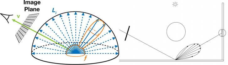
    // Work out contribution from reflected light
    // Diffuse reflection condition:
    // Create orthogonal coordinate system defined by (x=u, y=v, z=norm)
    double angle = 2 * M_PI * drand48();
    double dist_cen = sqrt(drand48());
    Vector u;
    if (fabs(norm.x) > 0.1) {
      u = Vector(0, 1, 0);
    } else {
      u = Vector(1, 0, 0);
    }
    u = u.cross(norm).norm();
    Vector v = norm.cross(u);
    // Direction of reflection
    Vector d = (u * cos(angle) * dist_cen + v * sin(angle) * dist_cen + norm * sqrt(1 - dist_cen * dist_cen)).norm();
Finally, we launch the ray in the given direction and record how much light is sent back. Depending on whether we are using explicit light sampling or not, we have two different paths. Emitter sampling cannot consider light emitted from the objects it hits due to double counting. For full details, refer to our paper.
    // Recurse
    Vector reflected = getRadiance(Ray(hitPos, d), depth + 1);
    //
    if (!EMITTER_SAMPLING || depth == 0) {
      return hitObj->emit + hitObj->color * lightSampling + hitObj->color * reflected;
    }
    return hitObj->color * lightSampling + hitObj->color * reflected;
  }
};
Setting up the camera
We first have a number of parameters that the user can modify to change the kind of sampling performed on the scene. EMITTER_SAMPLING turns on and off emitter sampling. $w$ and $h$ adjust the size of the image processed. SNAPSHOT_INTERVAL determines how many samples should be taken before another snapshot is taken. SAMPLES specifies the total number of samples taken. FOCUS_EFFECT turns on and off the focusing effect (see 'Focusing' section), and the FOCAL_LENGTH determines at what distance from the camera objects in the scene will be most in focus. APERTURE_FACTOR is used to divide the default aperture size in order to increase or decrease the field of view of the camera. We also specify which scene we want to sample.
int main(int argc, const char *argv[]) {
  /////////////////////////
  // Variables to modify the process or the images
  EMITTER_SAMPLING = true;
  int w = 256, h = 256;
  int SNAPSHOT_INTERVAL = 10;
  unsigned int SAMPLES = 50;
  bool FOCUS_EFFECT = false;
  double FOCAL_LENGTH = 35;
  double APERTURE_FACTOR = 1.0; // ratio of original/new aperture (>1: smaller view angle, <1: larger view angle)
  // Initialize the image
  Image img(w, h);
  /////////////////////////
  // Set which scene should be raytraced
  auto &scene = complexScene;
  Tracer tracer = Tracer(scene);
To change the field of view, we divide the aperture size by APERTURE_FACTOR, so a value > 1 results in a shallower field of view, and a value < 1 results in a wider field of view. Depending on the field of view, we have to move the camera either closer or farther away from the scene to display the desired image. For example, when the field of view becomes too wide, we begin to see the black background around the edges of the Cornell box. Conversely, if the field of view is too narrow, we only see the center portion of our image (essentially zoomed in). To fix, this we reposition the camera by recalculating $L$, the distance from the camera to the image plane. Essentially what this does is ensure that the rays that emerge from the camera subtend the same area in the image plane, regardless of their angle (dictated by aperture size).
  /////////////////////////
  // Set up the camera
  // Get new aperture size
  double aperture = 0.5135 / APERTURE_FACTOR;
  Vector cx = Vector((w * aperture) / h, 0, 0);
  Vector dir_norm = Vector(0, -0.042612, -1).norm();
  // Original distance from camera to image plane
  double L = 140;
  // Calculate new L to shift camera appropriately
  double L_new = APERTURE_FACTOR * L;
  double L_diff = L - L_new;
  Vector cam_shift = dir_norm * (L_diff);
  if (L_diff < 0){
    cam_shift = cam_shift * 1.5;
  }
  L = L_new;
  Ray camera = Ray(Vector(50, 52, 295.6) + cam_shift, dir_norm);
  // Cross product gets the vector perpendicular to cx and the "gaze" direction
  Vector cy = (cx.cross(camera.direction)).norm() * aperture;
We are now ready to take samples of our scene.
In this situation, we want to take $n$ samples, which is our outer loop.
Every set interval, we also save an in-progress snapshot in the temp directory so that we can check convergence.
  /////////////////////////
  // Take a set number of samples per pixel
  for (int sample = 0; sample < SAMPLES; ++sample) {
    std::cout << "Taking sample " << sample << "\r" << std::flush;
    if (sample && sample % SNAPSHOT_INTERVAL == 0) {
      std::ostringstream fn;
      fn << std::setfill('0') << std::setw(5) << sample;
      img.save("temp/render_" + fn.str());
    }
    // For each pixel, sample a ray in that direction
    for (int y = 0; y < h; ++y) {
      for (int x = 0; x < w; ++x) {
Variance reduction through adaptive sampling
As mentioned earlier, we performed a number of experiments using various adaptive sampling techniques. Unfortunately none of them worked particularly well. We left one of the rejection based methods commented out here. The overhead of estimating the variance and performing rejection sampling repeatedly for each pixel in the scene killed any computational benefits that we hoped to see. This is primarily as the code to perform sampling is fast enough that multiple samples could be taken in the time it would take to perform rejection sampling.
        /*
        Vector target = img.getPixel(x, y);
        double A = (target - img.getSurroundingAverage(x, y, sample % 2)).abs().max() / (100 / 255.0);
        if (sample > 10 && drand48() > A) {
          continue;
        }
        ++updated;
        */
Variance reduction using a tent filter
To ensure we do not have any hard edges, referred to as aliased edges, we want to slightly perturb the initial starting position of the ray each time. We could use random points pulled from the pixel's bounding box, but it turns out these are likely to result in aliasing. Restricting it to pixels from this area is referred to as a box filter.
Using a tent filter is an example of a quasi-Monte Carlo method. In certain problems, we know we would prefer something other than a pseudo-random sequence. With better chosen sequences of samples, usually low-discrepancy sequences, quasi-Monte Carlo has a rate of convergence close to $O(\frac{1}{N})$, whereas the rate for the Monte Carlo method is $O(N^{-0.5})$.
In our situation, we want to select a sequence that will provide better anti-aliasing than randomly chosen points. The tent filter is an example of a reconstruction filter (or anti-imaging filter) that is used to construct a smooth analogue signal from a digital input. Below is a scatter plot of the 2,500 points passed through a tent filter compared to 2,500 random points. Notice how the edges and the corners in particular are avoided. This prevents aliasing in situations such as a checkerboard heading off to infinity.
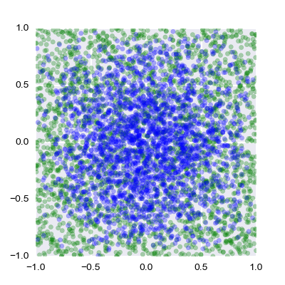
The green points are randomly distributed whilst the blue points are distributed according to the tent filter.
        // Jitter pixel randomly in dx and dy according to the tent filter
        double Ux = 2 * drand48();
        double Uy = 2 * drand48();
        double dx;
        if (Ux < 1) {
          dx = sqrt(Ux) - 1;
        } else {
          dx = 1 - sqrt(2 - Ux);
        }
        double dy;
        if (Uy < 1) {
          dy = sqrt(Uy) - 1;
        } else {
          dy = 1 - sqrt(2 - Uy);
        }
Focusing
The boolean FOCUS_EFFECT incorporates a focusing effect. This essentially changes the directions of all of the rays from each pixel so that they converge at a distance FOCAL_LENGTH from the image plane. The direction for each ray in each pixel is different, as the pixels are jittered randomly according to the tent filter described above. First, we calculate the focal point $fp$ from each pixel by extending the ray from the camera past the image plane out to the focal length. Then we find the point on the pixel point that the ray passes through, according to our tent filter. By subtracting the position of this point from the focal point, we have the new direction vector $d$ from the image plane into the image.
        // Calculate the direction of the camera ray
        Vector d = (cx * (((x+dx) / float(w)) - 0.5)) + (cy * (((y+dy) / float(h)) - 0.5)) + camera.direction;
        Ray ray = Ray(camera.origin + d * 140, d.norm());
        // If we're actually using depth of field, we need to modify the camera ray to account for that
        if (FOCUS_EFFECT) {
          // Calculate the focal point
          Vector fp = (camera.origin + d * L) + d.norm() * FOCAL_LENGTH;
          // Get a pixel point and new ray direction to calculate where the rays should intersect
          Vector del_x = (cx * dx * L / float(w));
          Vector del_y = (cy * dy * L / float(h));
          Vector point = camera.origin + d * L;
          point = point + del_x + del_y;
          d = (fp - point).norm();
          ray = Ray(camera.origin + d * L, d.norm());
        }
        // Retrieve the radiance of the given hit location (i.e. brightness of the pixel)
        Vector rads = tracer.getRadiance(ray, 0);
        // Clamp the radiance so it is between 0 and 1
        // If we don't do this, antialiasing doesn't work properly on bright lights
        rads.clamp();
        // Add result of sample to image
        img.setPixel(x, y, rads);
      }
    }
  }
  // Save the resulting raytraced image
  img.save("render");
  return 0;
}